Tasmanian Racing Drone - Build Log #4
Housekeeping
This is the fourth article in a series of build logs I’m writing for Catalyst Machineworks’ Tasmanian V1 beast class/X-class racing drone frame. If you missed the others, follow along:
Tasmanian Drone Racing - Build Log #4 (you are here)
I purchased this frame and a bunch of components in the summer of 2019 and finally got some free time to work on this build! This is a ridiculously sized racing platform with 13” tri-blade props, 345KV motors, all running on 50V of electrical goodness.
Disclaimer: this isn’t my first drone build!
Much of this build log is a stream of consciousness as I’m working through the build - no real attempt to structure anything. While I am still in a learning mode (as we all are), I do have an idea as to how dangerous a build of this size can be. I’ll be taking plenty of precautions as I go through this, and I’ll be sharing them with you as I go, lessons learned and all. If you have constructive feedback, I would love to hear it!
This is a big update! Let’s get into it.
Fit Tests
On our last episode, I left you with an all-up 50V power-on systems test video. You can check that out in build log #3 here. Here’s a few random fit tests with some notes.
Before I could fully install the flight stack into the frame, I needed to finish a few important details, determine order of operations for install, and do some fit tests to ensure that the video transmitter and radio receiver would have enough clearance.
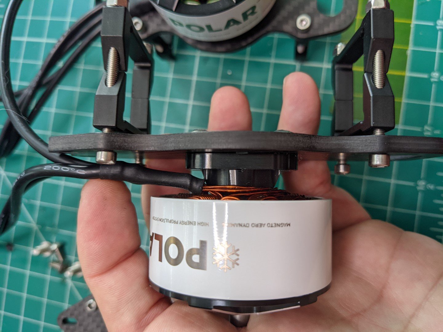
I also found that the fasteners that MAD Motors included had socket heads that were a bit too long for these motor mounts. Thankfully, Catalyst included M4 button head fasteners that clear the square carbon tubes. More on the motor installation coming up.
Lastly, one of my cats performed some early QA testing and “fixed” one of my antennas. I’ll eventually be replacing these with longer 100mm antennas. ;p


Systems Integration
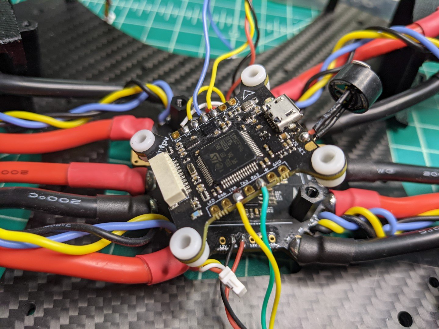
Next, the finishing touches and installation of the flight control stack into the frame. I started by finishing the heat shrink at the PDB and ESCs. After that, I added some vibration dampening grommets to isolate the flight controller (a bit) from the central 30mm x 30mm nylon screw mounts. These are shipped with the BrainFPV Radix, and recommended by Catalyst, so I figured they would be acceptable for this build.
Motor Installation
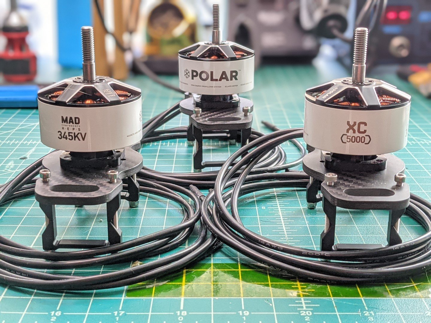
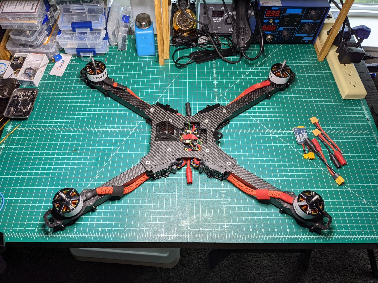
Now that all the systems are in place and function checked, it’s time to assemble the rest of the frame! Each arm is partially installed, then the top plate is attached since this is what sandwiches the arms in place. I attached the motors to each mounting bracket, and each bracket to an arm, to make assembly a bit easier on my tiny bench. It’s just really too large for the amount of room I have currently! I love it.
Here you can see some of the process I went through to install, size, and cut the wires. I did end up swapping out the motor/bracket fasteners from the factory-supplied socket-head, to the Catalyst-supplied button head, which I mentioned previously. You’ll see a few of those images here as well.
I snuck in a quick prop tip check to make sure these massive 13” Master Airscrew 13x12x3 props will actually fit! More in depth motor/ESC wiring is next!
Motor Wiring
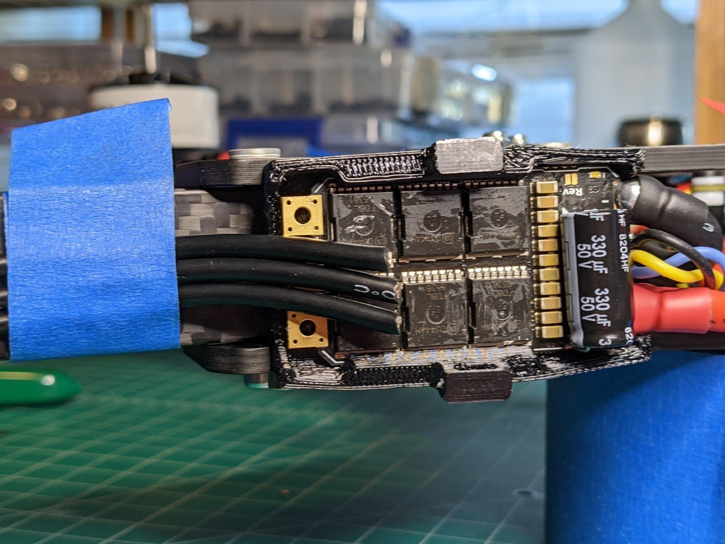
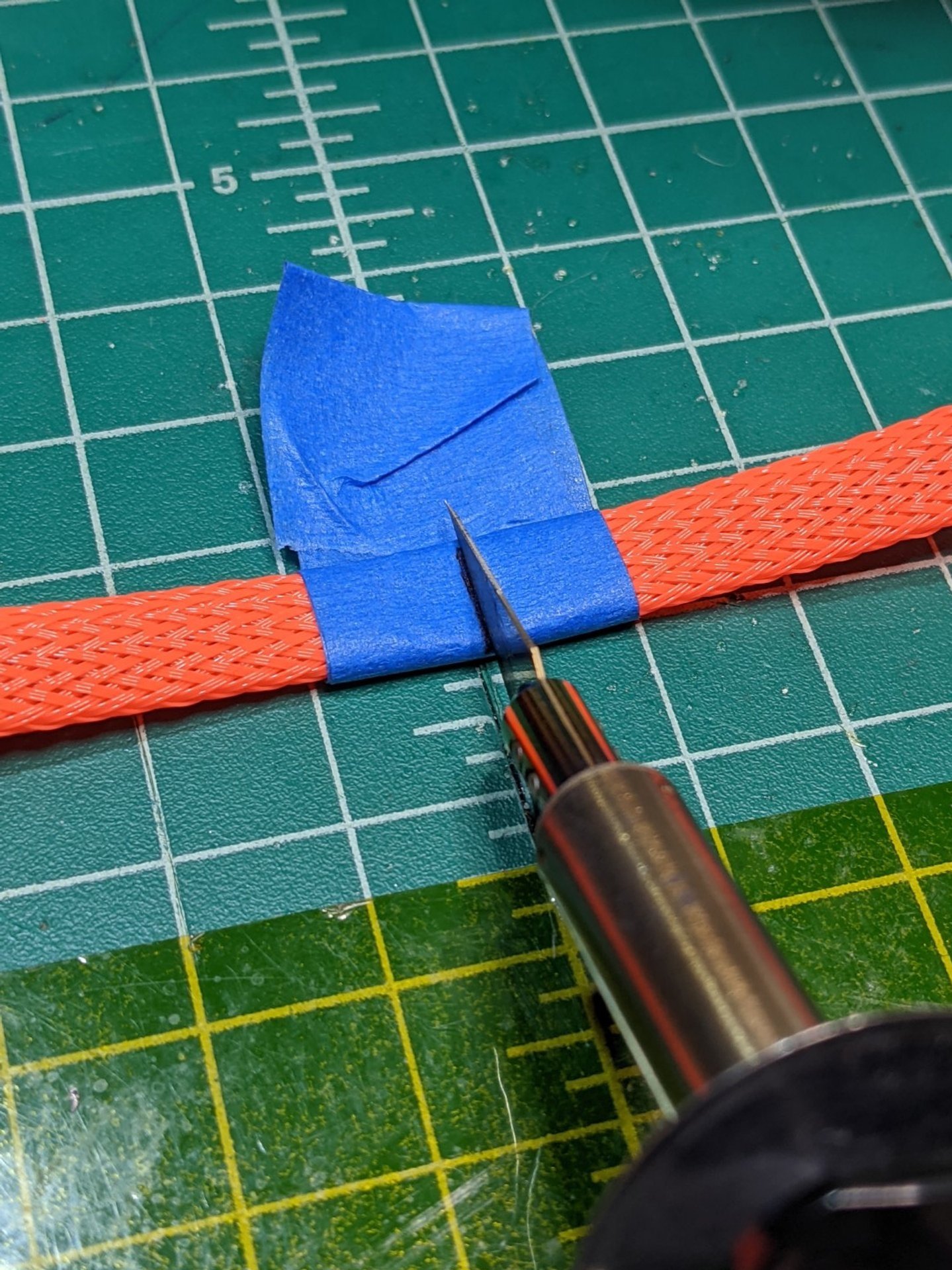
I had forgotten to tin my ESCs on a previous step, so I took care of this right before final install. After that, I sized some orange wire mesh that will wrap - and kind-of protect - the motor wires. I’m not a huge fan of the mesh for this build honestly. It buckles at the bend closest to the motor because it’s not meant to bend to such a large degree. Adding 3:1 heat shrink helps a bit, but I still am bothered by it. We’ll see how it looks after the build is complete. I may swap motors in the future anyway!
To keep the mesh from fraying at the ends, I took a lighter and melted a ring of plastic around the ends. To slip wires in, it’s helpful to open up the mesh by compressing it like an accordion. You’ll see some of these methods below.
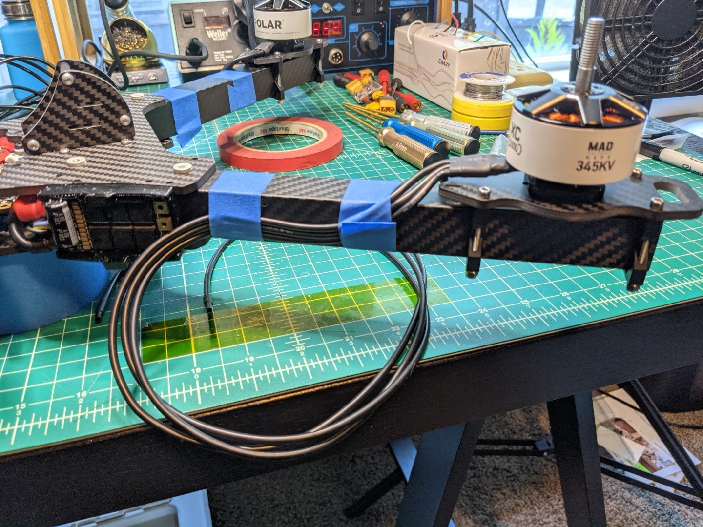
I go through a bunch of blue tape until I eventually gave up and used zip ties to keep everything in place for soldering. I needed a more solid temporary mounting solution to keep the wires from moving on me during install. You’ll see when that transition happens. Live and learn.
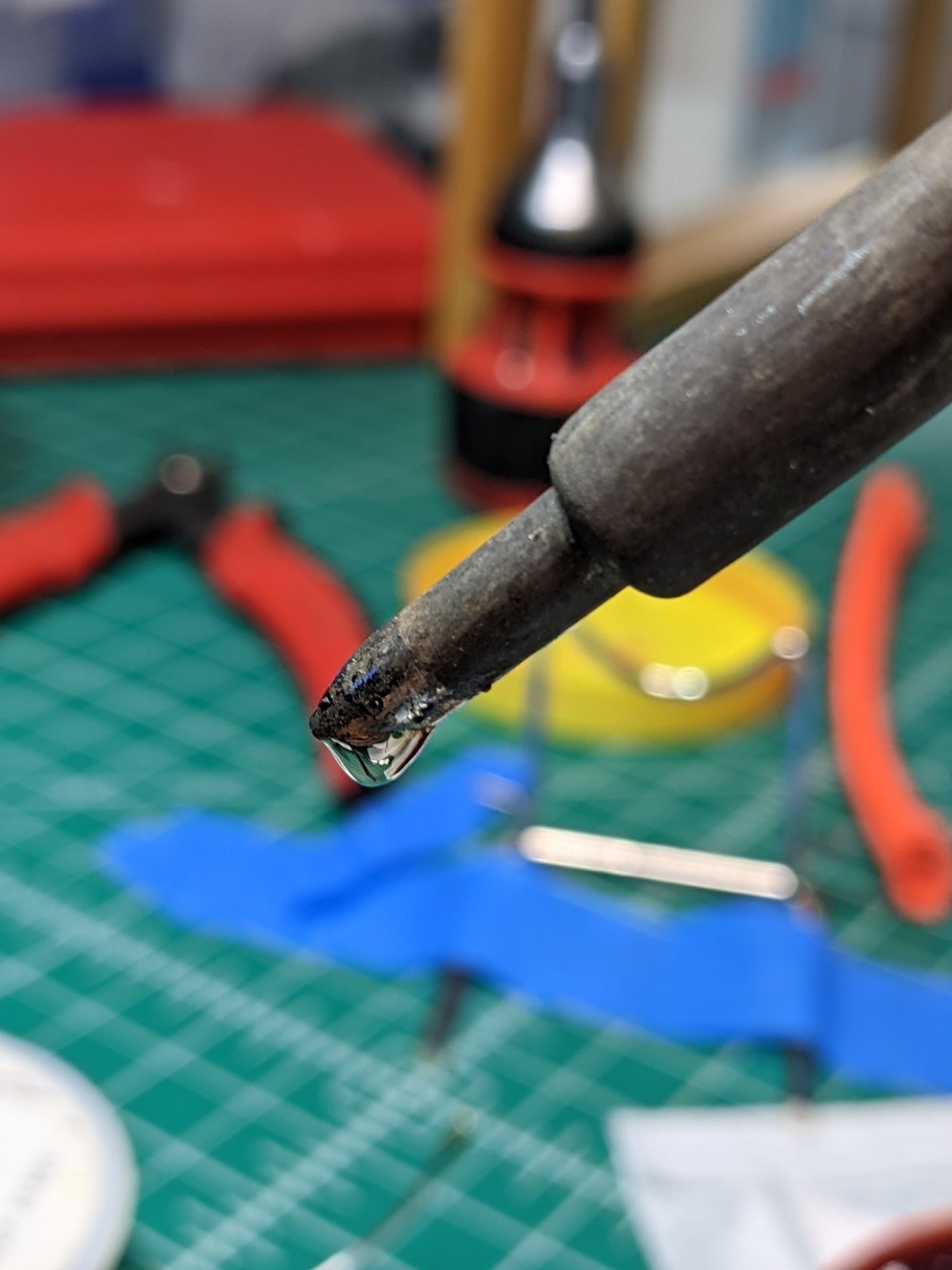
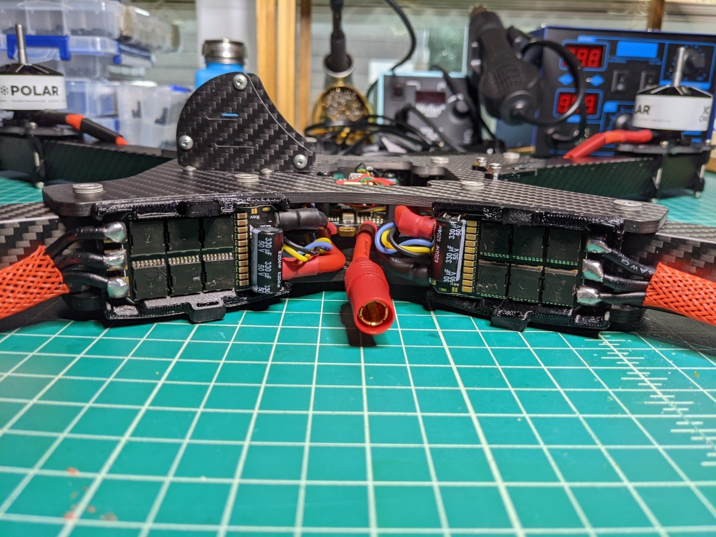
Lastly, soldering the motor wires to the ESCs is super fun with these huge pads! After tinning the ESC pads, tinning each wire, and slathering the whole thing with a mess of flux, I load up solder on my iron tip (shown below), and carefully bring it to the pad. I let the bubble of solder envelop itself around the wire and pad, and then I press down gently. The entire solder joint then begins to flow together. After a few seconds, I carefully remove the iron, and keep the wire held in place securely with a pair of tweezers. After a few seconds, the joint begins to harden, leaving a fully flowed joint.
Also pictured is my janky solution to soldering the wires in-place. I didn’t feel comfortable holding the quad in my lap to keep the ESC pads flat, so I ended up clamping it (in the right orientation) to my bench light. It worked, and was fairly stable, but not a very solid solution.
Power On / Motor Functional Test!
Basic functional check on the motors was needed to confirm a successful wire job. I had previously verified all of the existing subsystems were correctly powering on and wired up. I simply needed to make sure the ESCs were correctly receiving a valid PWM signal, the ESCs could detect the motors, and that each motor was working as intended.
Next Steps
Coming up, I’ll be focusing on configuration in betaflight. We’ll be selecting motor direction (including a discussion on how to accomplish this with these particular ESCs), radio configuration + failsafe setup, video configuration, and finishing up the last minute details. I’ll also begin work on a 3D printed enclosure for the radio/VTX boards and antennas.
Lessons Learned
Use double sided tape, or something similar, to keep the 330mf capacitors fixed to the ESCs. It’s too easy to bend them out of position if they are only mechanically held on by their two leads. Additionally, they are awfully exposed with the ECSs on the side of the frame - suseptible to sticks and debris during flight. I’d like to figure out a method of protection for them.
Using blue painters tape to size the motors wires was helpful only to a point. By the time I added heat shrink and wire mesh, it was far too heavy for tape to work. I ended up using zip ties to temporarily hold wires in place for me to finish cutting to length and for solder work. This worked a lot better, if more wasteful.
I’m not sure I would use wire mesh for motor wire protection on this build. I don’t like how it compresses at sharp bends near the motor. Mesh isn’t really built for tight bends. An alternative method to protect the wires is desired. Not sure I have a good solution yet. Note: I did think about routing the motor wires through the carbon tube (like many of the other X-class builds do, but that would introduce a few other issues with soldering up the ESC and routing wires through the carbon frame stack.
Avoid gripping too tightly when using sharp tweezers to hold insulation/wire. I definitely cut a bit of insulation when installing motor wires in a few spots. Since these will be covered with heat shrink, it’ll be fine for initial testing. It’s not a great long term solution - these motors will end up being replaced in the future. Be safe and switch to blunt-nose tweezers when using soft insulated wire.
Ensure the pads you are soldering on are flat! Any angle, and the solder will flow off. Ask me how I know.
My method of soldering on the vehicle is totally jank. Clamping it in place to my light fixture arm is definitely NOT a great solution. It did turn out ok, but was a little sketchy.


