Tasmanian Racing Drone - Build Log #3
Housekeeping
This is the third article in a series of build logs I’m writing for Catalyst Machineworks’ Tasmanian V1 beast class/X-class racing drone frame. If you missed the others, follow along:
Tasmanian Drone Racing - Build Log #3 (you are here)
I purchased this frame and a bunch of components in the summer of 2019 and finally got some free time to work on this build! This is a ridiculously sized racing platform with 13” tri-blade props, 345KV motors, all running on 50V of electrical goodness.
Disclaimer: this isn’t my first drone build!
Much of this build log is a stream of consciousness as I’m working through the build - no real attempt to structure anything. While I am still in a learning mode (as we all are), I do have an idea as to how dangerous a build of this size can be. I’ll be taking plenty of precautions as I go through this, and I’ll be sharing them with you as I go, lessons learned and all. If you have constructive feedback, I would love to hear it!
At this point in the build up, I have confirmed that the main power distribution subsystem is functional. Next, we need to get the rest of the vehicle subsystems soldered in and integrated into the flight controller. After that, we’ll do another system power on to verify no shorts anywhere in the electrical systems! Let’s get to it.
Subsystems Integration
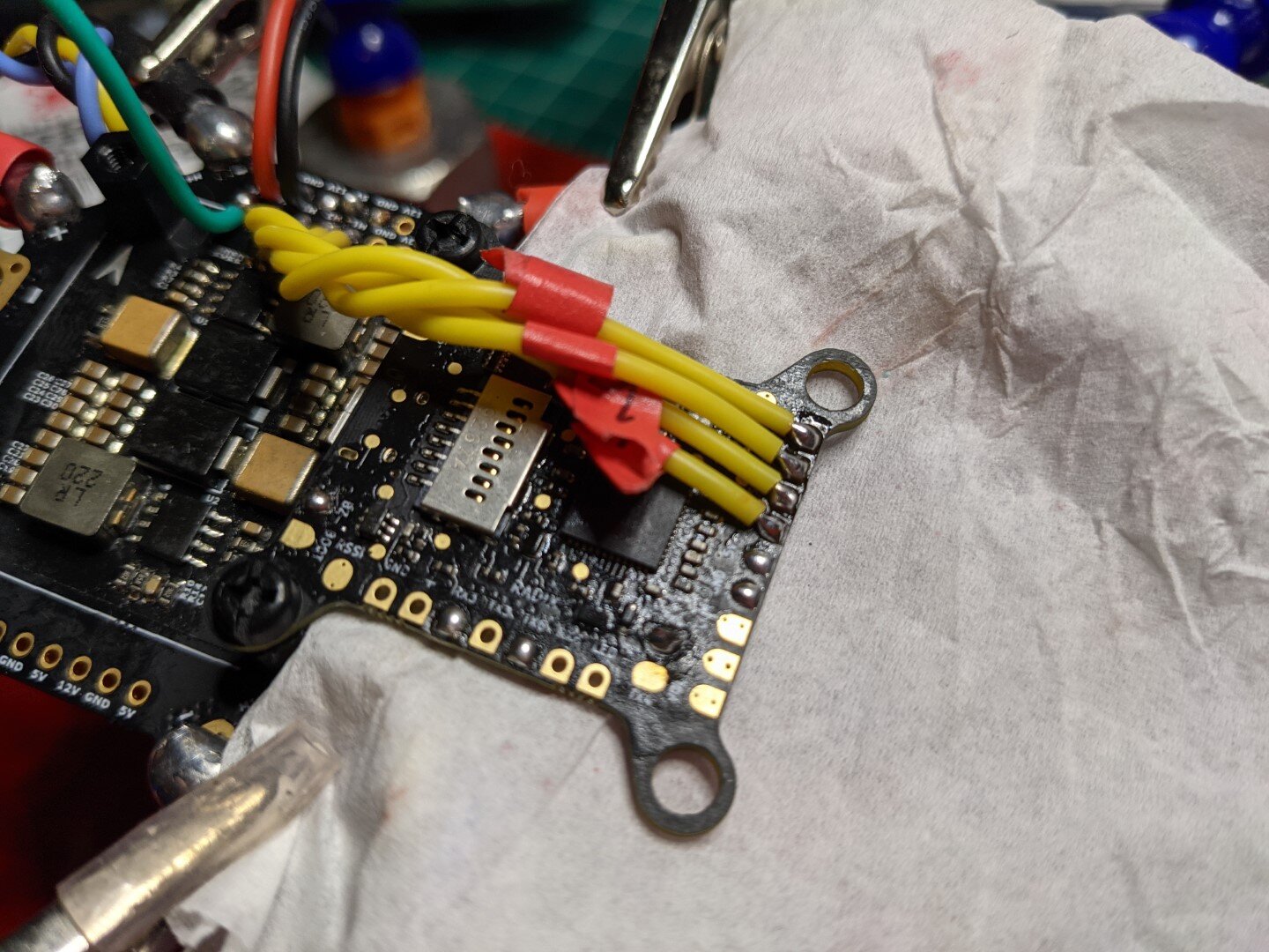
I started by tinning the pads on the BrainFPV Radix flight controller according to the I/O on my wiring diagram. See log #1 for reference. For these flat pads, I switched to a smaller chisel tip, and added solder accordingly. The pass-through holes make things a bit more challenging, so I did my usual, and flipped the board upside down. This allows gravity to pull the solder down through the hole, while surface tension pools the solder in a bubble on the opposite side of the pad. Note: it doesn’t always work. YMMV.
Flight Controller
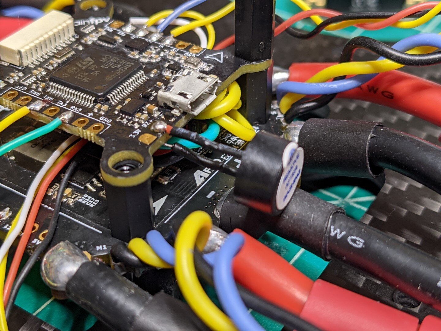
Next, I spent a bit of time determining wire routing since the flight controller stacks on top of the power distribution board. This particular flight controller happens to be double sided, which will make it a bit more difficult to install once everything is connected. I decided to install the 7 wires on the underside first, which would allow me to flip the board, secure it, and finish the other side from above.
I ended up using some 22 guage flexible silicone wire, but in retrospect, I think 26 might have been an acceptable alternative given how little available space there was in between the boards. The wires underneath turned out to be a little cramped as a result, and are gently resting on the PDB underneath. I might need to change this in the future - we’ll see if this poses an issue during ground testing. I also chose not to install the rubber isolation mounts until after all the soldering activities are complete.
Camera and Video Transmitter (VTX)
I started by trimming and tinning the wiring harnesses that came with each device. The Camera is a Runcam Micro Eagle. These are at least 30 gauge and pretty delicate. I soldered the power and ground pins for each device together based on recommendations from Josh Bardwell, and other builds I’ve seen. I’m going to experiment with navigating camera on screen display (OSD) menus from Radix using their camera control (CC) feature - we’ll see how it goes!
I removed the ground wire from the camera controller plug since that hasn’t seemed to be an issue for past builds. I suspect this ground wire is really to ensure the physical controller is looped into the same ground plane. Note: I am choosing to keep harnesses long until I have everything integrated and checked out. Once the various positions of hardware is locked, then I’ll most likely shorten wires.
The careful PDB wiring is slowly being obscured by a rats nest of cable harnesses with all these accessories being integrated. Oh well. After everything was wired up, I did another power-on test to verify good video. I took a quick shot through the goggles just to functional check everything. Bonus: cat.


Radio Receiver and Beeper
The last of the main electronics to go in are the FrSky R-XSR radio and a low voltage beeper. The R-XSR will take power/ground from the PDB, TX6 will be SmartPort and RX3 will be SBUS Out. At some future point in time, I may hook up a second R-XSR to take advantage of the redundant pass-through feature and test to see how well it works. It might be neat to connect up a wireless switch and test a few different types of failsafes on ground to see how the redundant hardware fares.
The beeper is installed simply to be a loud beacon in case of a crash. This will be turned on and off from my radio transmitter.
Full Systems Power-on Test
Before I start locating the final positions for the hardware, I did one last systems power-on. With this gate cleared, I am ready to install motors and finish the assembly!
Lessons Learned
Consider using a smaller gauge wire for ESC telemetry, PWM signal, and low power DC for the flight controller. 24/26 would work better in this scenario than 22 given the cramped installation area, and the proximity to the PDB inductors / capacitors.
Spend a bit more time finding a good hand placement when soldering in-place on a complicated build like this. I felt like I was rushing, and the quality of the solder joints for some of these accessories was not my best. This should be ok for testing, but I would not pass this build if it were for anything more formal.
Next Steps
I’ll be spending some time next on sizing the motor wires to the ESCs, and choosing a solid route for my wires to minimize potential prop strikes. After I get the motors installed, I’ll begin working on the Betaflight configuration including ESC protocols, functional motor checks, and radio modes, and failsafe config. This is where I get to bring this beast to life!
I also need to figure out where and how to install the VTX and radio receiver into the frame permanently. These small boards are loose for testing right now, but this is not the final configuration to conduct ground and flight testing. Since I have access to several different 3D printers, I’ll most likely design and print some custom brackets to work with this specific frame. I will also need to route the radio antennas underneath the arm using some sort of 3D printed bracket as well. I’ll share the process as I get there!
Getting closer :D


