Tasmanian Racing Drone - Build Log #1
Update #1 - 08/27/21: Added v2 of my wiring diagram. I still might move the current Cam/VTX power wiring to the PDB, but i’m pretty happy with the architecture so far.
Update #2 - 9/10/21: Added links to build log breadcrumb.
Update #3 - 10/29/21: Added new build log links!
This is the first article in a series of build logs I’m writing for Catalyst Machineworks’ Tasmanian V1 beast class/X-class racing drone frame. If you missed the others, follow along:
This is the Catalyst Machineworks Tasmanian V1.
I purchased the frame and a bunch of components in the Summer of 2019 and finally got some free time to work on this build! This is a ridiculously sized racing platform with 13” tri-blade props, 345KV motors, all running on 50V of electrical goodness.
Much of this build log is a stream of consciousness as I’m working through the build - no real attempt to structure anything.
Disclaimer: this isn’t my first drone build!
While I am still in a learning mode (as we all are), I do have an idea as to how dangerous a build of this size can be. I’ll be taking plenty of precautions as I go through this, and I’ll be sharing them with you as I go, lessons learned and all. If you have constructive feedback, I would love to hear it!
Hardware
I’ll be following similar hardware choices as recommended by Catalyst Machineworks in 2019, with exception of the radio receiver. In an effort to reduce the amount of new tech i’ll be soldering, I’ve opted not to go with a TBS Crossfire. Instead, I’ll be using a radio I’ve put on several past builds: FrSky R-XSR. Note that this is for testing only. I 100% agree with Catalyst Machineworks’ recommendations for a more stable protocol, but I also won’t be racing or doing anything public with this build. This is for experimentation only. I do plan to integrate Crossfire at a future date.
Flight Controller: 1x BrainFPV Radix
Power Distribution: 1x Advanced Power Drives (APD) PDB500[X]
Camera: 1x RunCam Micro Eagle
VTX: 1x TBS Unify Pro 5G8 V3 (SMA) (5V version!)
Radio: 1x FrSky R-XSR (2.4 GHz ACCST)
Propeller: 4x Master Airscrew 3x13x12
Motors: 4x MAD XC5000 POLAR 345K
Battery: 2x 6S HRB 4000mah 60C
Other Items
10 guage multi-stranded copper wire (silicone insulated)
22 guage multi-stranded copper wire (silicone insulated)
Flux! I use RubyFluid Flux Paste with a brush
Weller WESD51 Digital Soldering Iron w/ variety tip set
4.8mm Chisel tip (something this large is required for these large joints)
60/40 Leaded Solder (it’s what I have!)
Kapton Tape
Wiring Plan
The very first thing: a wiring plan. For my builds, I like to draw up a wiring plan by hand so I can determine what power and communication busses I have available to me, a basic layout (notional only), wire colors, and a map of all the hardware and their specific I/O.
Version 1 and 2 are included below. Much like Adam Savage, I’ll be doing a few more of these sketches as I go. I’ll include future versions here as I tweak the design based on what I learn.
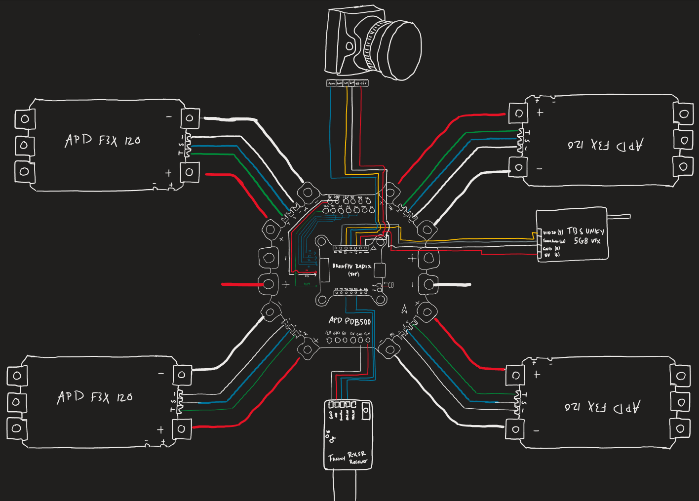
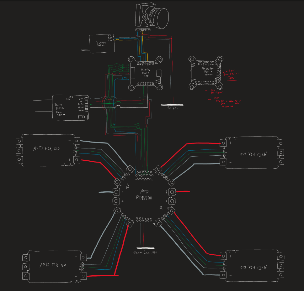
Since the PDB has some decent space on the drawing, my second version of this will feature the Radix flight controller drawn on top of the PDB. It will look a bit neater for my needs, and I’ll have less wire routing on the drawing to make. I’m also planning to move my VTX and camera to the same 5V/GND lines based off what I’ve seen on Catalyst Machineworks’ build, and Josh Bardwell’s build video.
Hardware Prep
I first started by conformal coating the PDB, flight controller, and ESCs. This was a new process to me, so bear with me as I explain more. Applying by brush created inconsistent application, as well as brush strokes which you can see in all my images. Not super happy with it, but i’m glad I learned about it. I did not apply conformal to any buttons or connectors to avoid any issues with blockages after it dries.
I did one application on each side of the boards as a precaution only. I suspect there was already some applied during manufacturing.
In hindsight, for next time, I should have masked off the pads. Yes, this particular type of conformal coating is able to be burned off using a solder tip, but in practice, it led to inconsistent peeling and gooping at the edges of the solder joints. I don’t particularly like cleaning and scraping it off. Theoretically, this shouldn’t cause any high voltage arcing, but i’m being overly cautious.
Also, this stuff is quite toxic. Make sure you use gloves, work in a well ventilated area, and try not to get much of it on your skin. There is a plethora of warnings and instructions to read in the box.
ESC Signal Wires
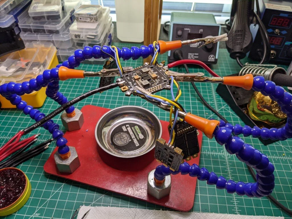
I started tinning pads and 22 guage wire with a smaller chisel tip. After a bit of troubleshooting and experimenting with the scalloped, sideways pads on both the ESC and power distribution board, I got the hang of it. I was able to place the small solder tip sideways in the cylindrical pad, and get a nice flow of solder started, gently pressing the soldering iron and wire into the channel. I suggest not starting with with the GND pads first as they do have quite a lot of thermal ground layer to heat up before they take the solder. The signal and telemetry pads went very smoothly.
Also, I love using the bent tweezers to hold the wire securely in place. Up until now, I’ve been using traditional tweezers and struggling to get enough leverage on the wire to push it where I need. The bend allows me to lay the wire, following the contour, and really grip the entire length. Placing the tinned tip became super easy!
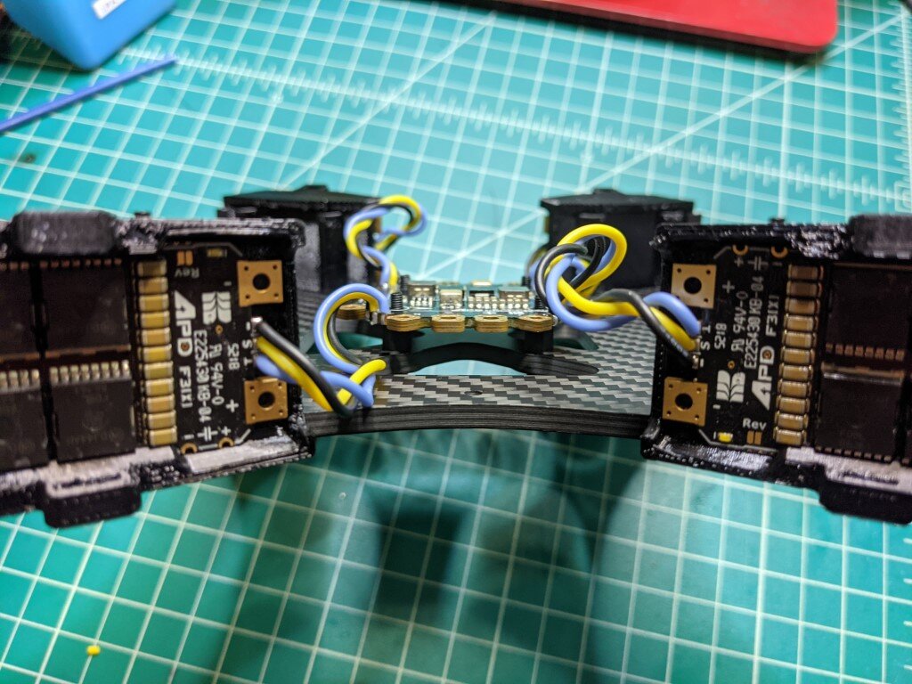
I made sure to create enough slack with the signal, ground, and telemetry wires to allow for the carbon fiber arms that sit right next to the 3D printed ESC mounts. Not too pleased with the twist yet, but we’ll see how things come together in the next few build logs.
Power Distribution Board (PDB)
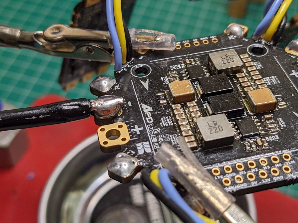
I needed to experiment a bit with these large power/gnd pads - they have giant holes connecting the top and bottom. Trying to leave solder on these was difficult, but again, it just took a little persistence. My iron was sitting around 410C (770F) for much of this using the largest tip I have: a 4.8mm chisel.
I was having trouble using Josh Bardwell’s technique of tinning and slowly lifting the solder tip off the pad while you feed more solder in (creating a sort of solder pillow). I thought about it for a bit, and tried again, this time flipping the board. This let the solder liquify and drop through the hole, which pools underneath nicely due to gravity! You’ll see this in the images below.
I should point out that it’s not totally easy to know how much solder has pooled. Be careful not to solder this way with any electronics nearby or underneath. If you drop solder, be prepared for splatter!
Lastly, the 10 guage wire I got is a little disappointing. While it is a bit flexible, the strand count is quite low, and the insulation does not hold heat very well. You can see me trying out a few different bend patterns with the wire, and it really holds its shape. I ran a number of tests and ultimately wasn’t satisfied with this. If you look closely enough, you can see that some of the insulation has melted closer to the solder joints.
I've purchased more anti-spark connectors and different 10 guage wire with a larger strand count. Hopefully this will hold up better under the heat, and improve the connect/disconnect endurance of these wires when paired with my battery leads.




Next Steps
I’ve ordered some replacement wire and more anti-spark connectors, as I mentioned before. I’ll be connecting up the battery leads to the two 6S batteries, and soldering up a few harnesses to connect to my battery charger. These batteries are in need of a good balance to storage charge.
After that, I’ll be connecting power and ground wires from the PDB to each ESC, adding capacitors to each ESC, and then conducting a few power system checks. I’ll start with my voltmeter to check continuity, and then try out a 3S or 4S battery so I can verify power to each ESC, and that the 5V and 12V regulators are working as expected. I don’t want to involve any other electronics at this stage in case something goes horribly wrong.
Lessons Learned / Helpful Hints
I like to be transparent about the things I learn. Figure they’re worth sharing and/or summarizing as I go. I plan to include more of these in future build logs.
When working with Conformal Coating, do so outdoors, with gloves, and preferably a mask of some type. These vapors are strong, and I can’t imagine they are great for you. Consider the warnings included before doing your own application. Be educated about this.
Mask the pads before conformal coating to prevent caking, and peeling after soldering.
Consider waiting until after soldering most of your components onto your electronics to apply the conformal coat. You do want to cover the solder joints as well. I avoided this at first because I was concerned that after putting everything together, I wouldn’t be able to take all the electronics out. This was a silly assumption. I’ll need to do another application after everything is done anyway, so just do it once at the end instead.
Using an angled pair of tweezers (like the ones from iFixIt) are extremely useful when holding wires! I was able to curl the wire to follow the contour of the grips, which gave me extremely fine control over the tinned tip.
Flipping the PDB and allowing the solder to pool underneath the pad created a great solder joint for me to run the 10 guage wire into.
Cheers!


