Laimer 600W 3D Printed DC Brushless Motor Build
Very excited about this project! Let me catch you up.
I’ve been interested to learn how the internals of a brushless DC motor work. This project by Christoph looked like a fascinating way to connect a bunch of fun projects. 3D printing, new filament materials, 3-phase copper wiring with the Halbach array, custom arduino PWM controller with logging.
The motor is designed by Christoph Laimer in 2017. All parts are printed from project files via MakeSEA. If you have any questions, let me know. The process to acquire a license to the parts was super easy, and I’m happy to support him.
Diameter: 105mm
Height: 85mm
Shaft: 8mm
KV: 225
Weight: 900g
Looks to be measured at 225 Kv, with a total weight of ~900g. We’ll compare that to mine when it’s complete.
PETG Parts
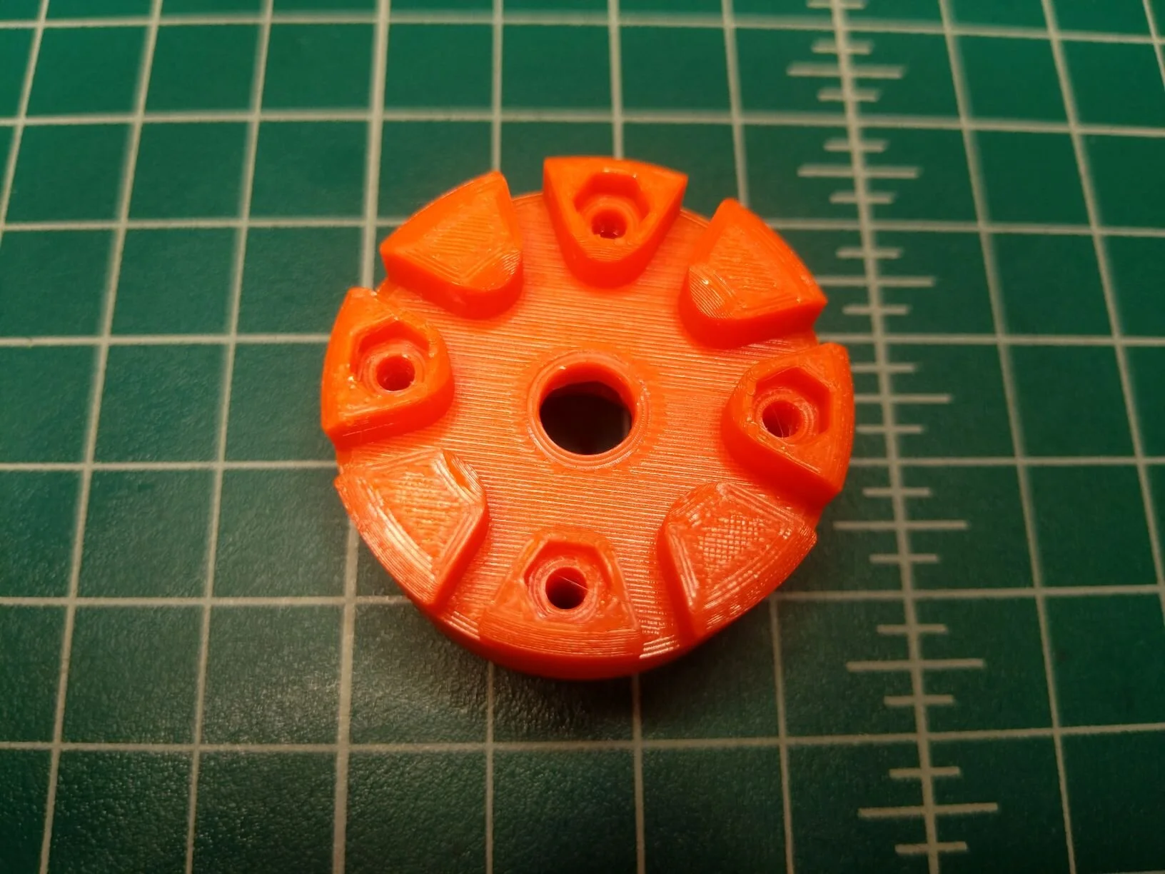
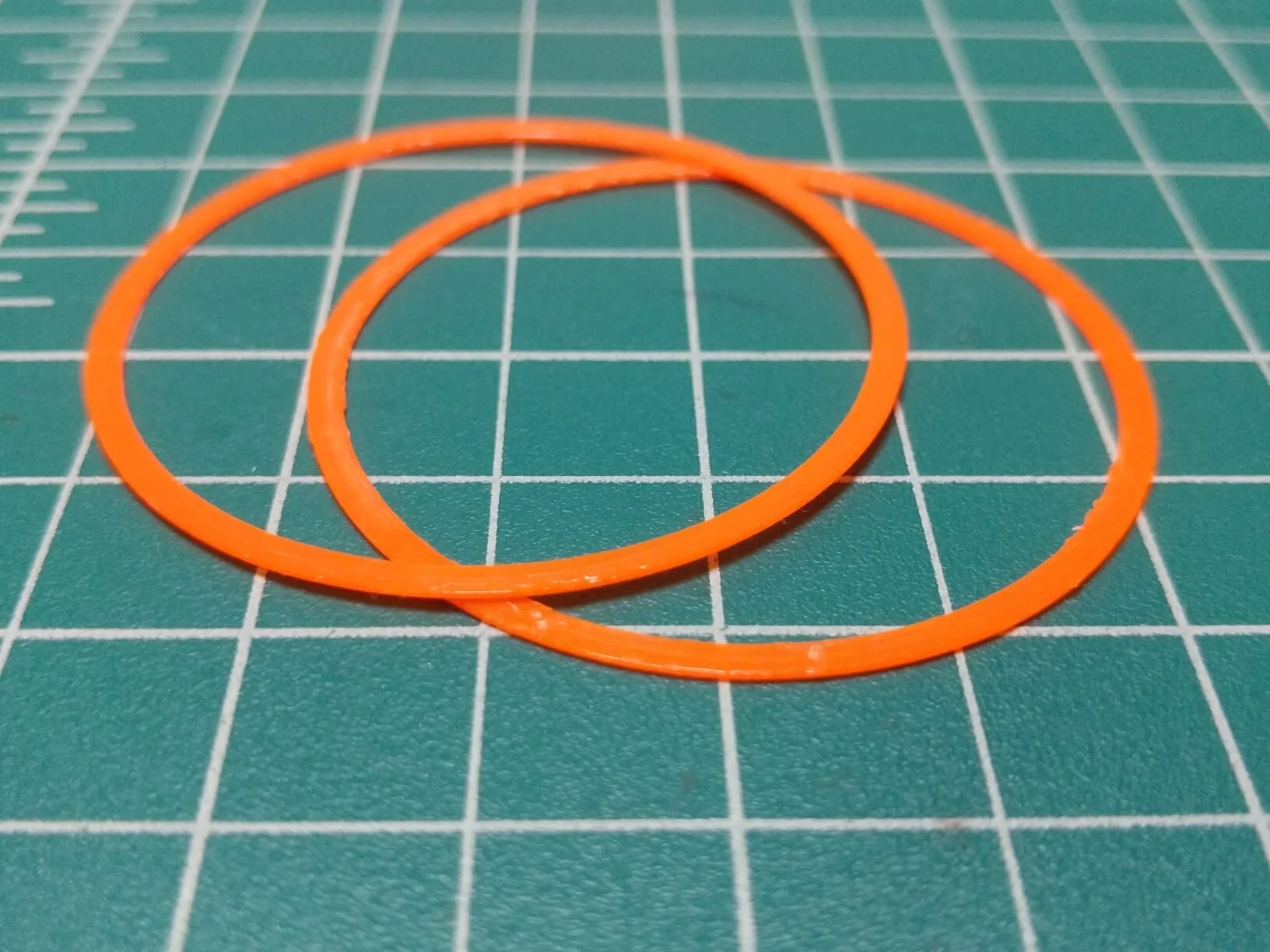
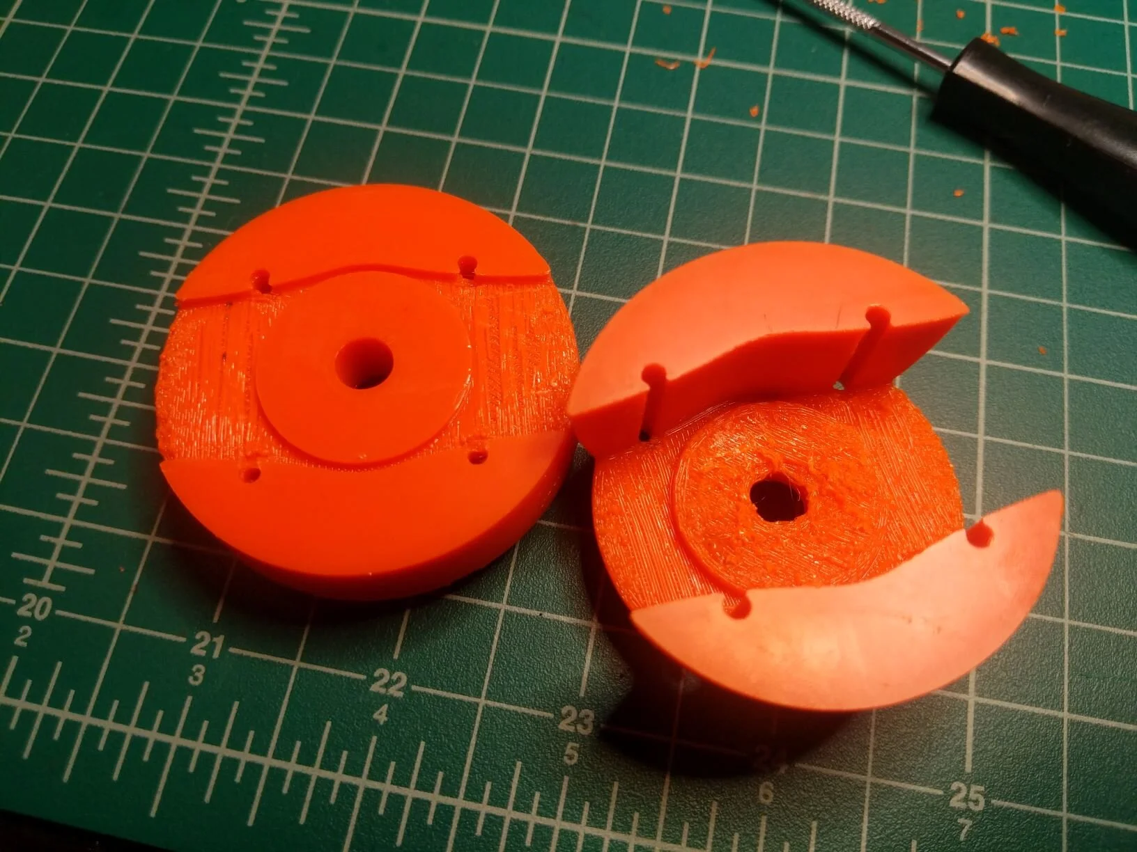
Printing the stator mount upper and lower out of PETG, as recommended. I tried a PLA version as well for fun, much lighter and brittle. Overall, my PETG settings needed a bit more work, but these should be good enough to test with. The 8mm collar and wire tool are printed next, followed by the upper rotor bell and lower twist cooling/balance ring.
I also printed the alternative colar system to clamp onto a large propeller - including extra reinforcement of the main shaft.
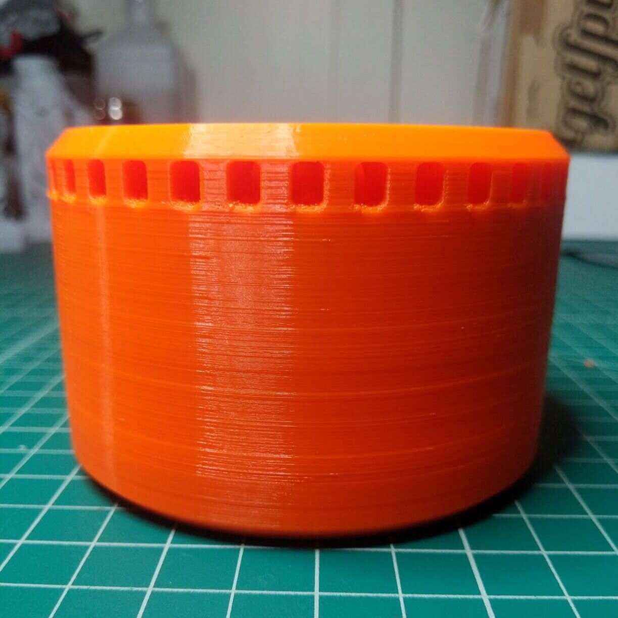
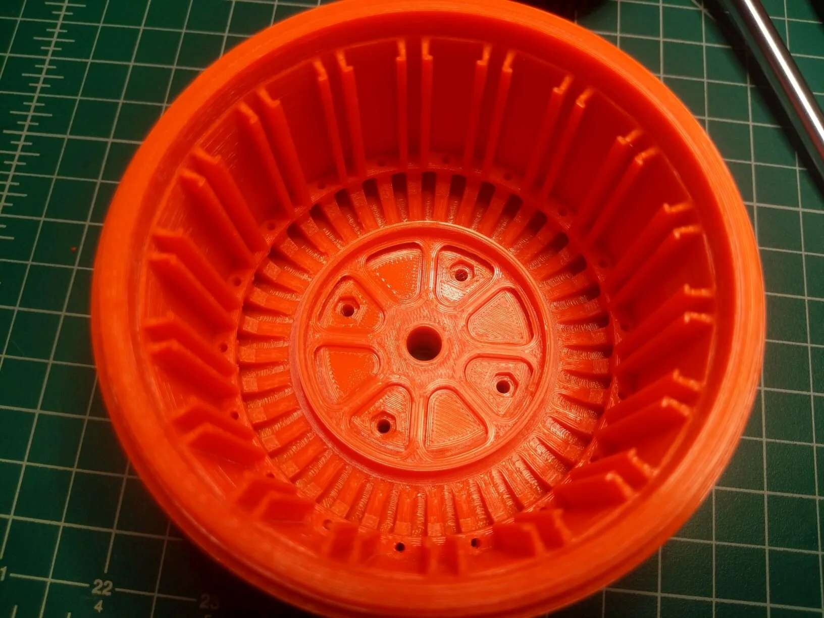
You can see all the channels for the magnets on the inside of the upper bell.








Ferromagnetic Iron PLA
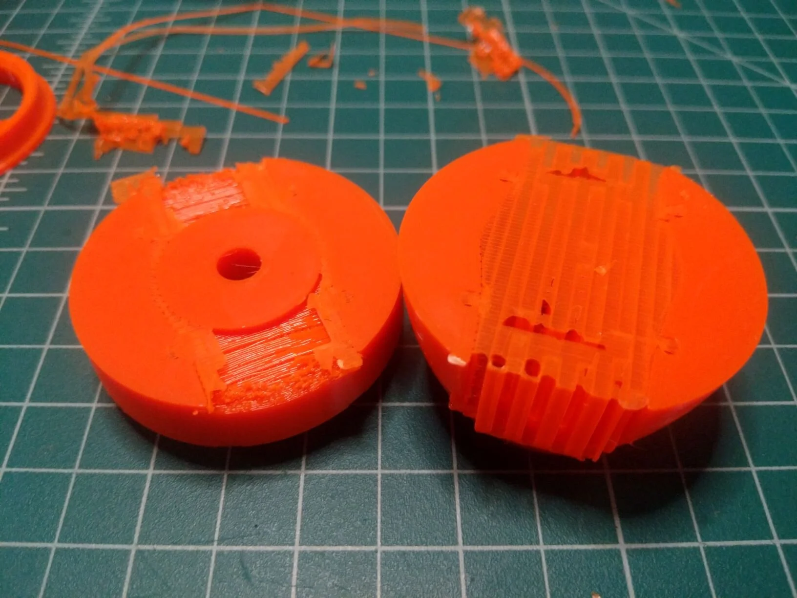
This stuff is amazing! This was my first time experimenting with a steel nozzle. Helpful due to the abrasive nature of the composite material being extruded. Note the minor layer separation in the calibration cube, and some edge lifting between each half of the iron core. The wispy filament can be lightly remolded back into the material with some hot air.
Hardware
Bearings, copper wire, magnets. You can see the full bill of materials at MakeSEA and Instructables.
Fitment
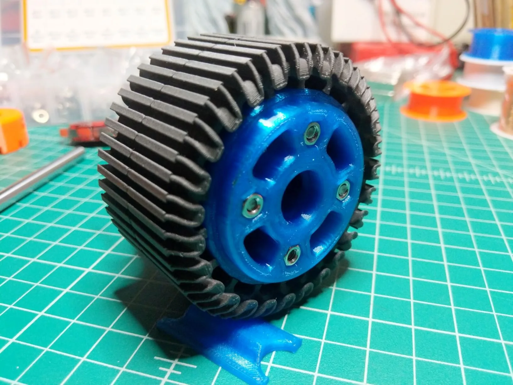
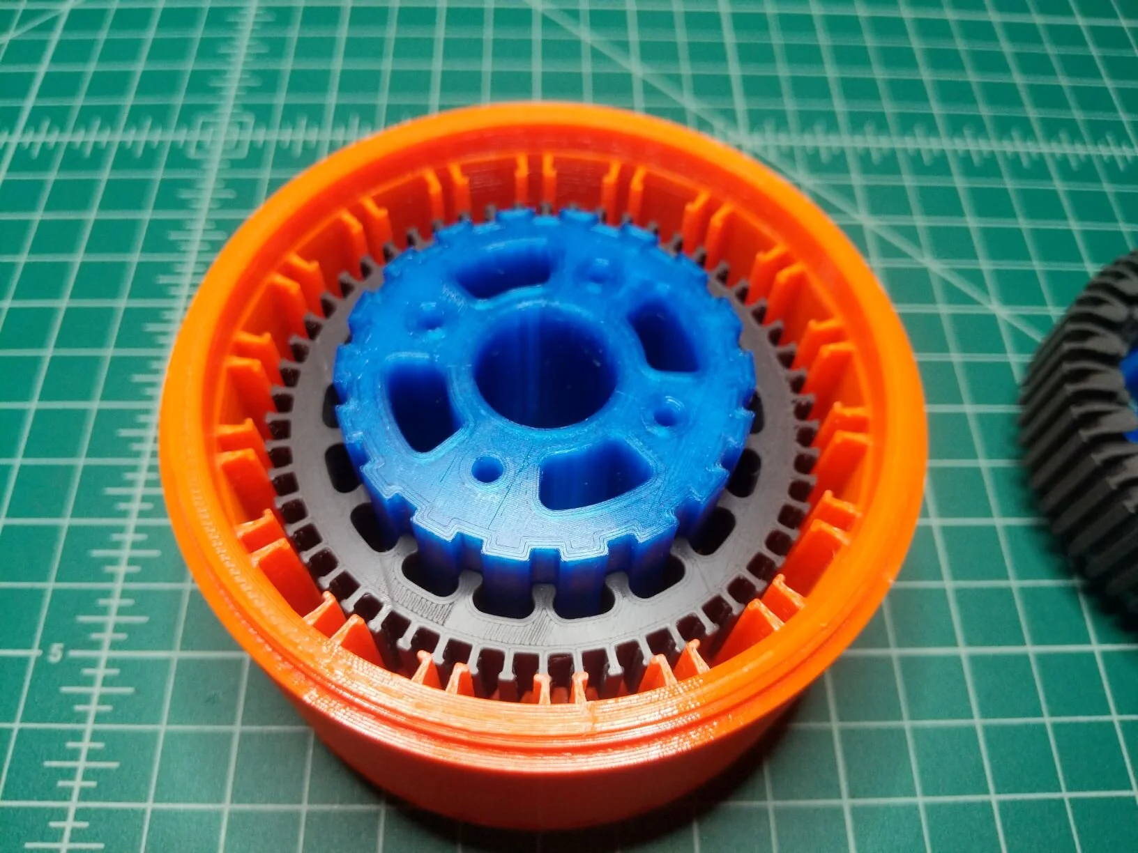
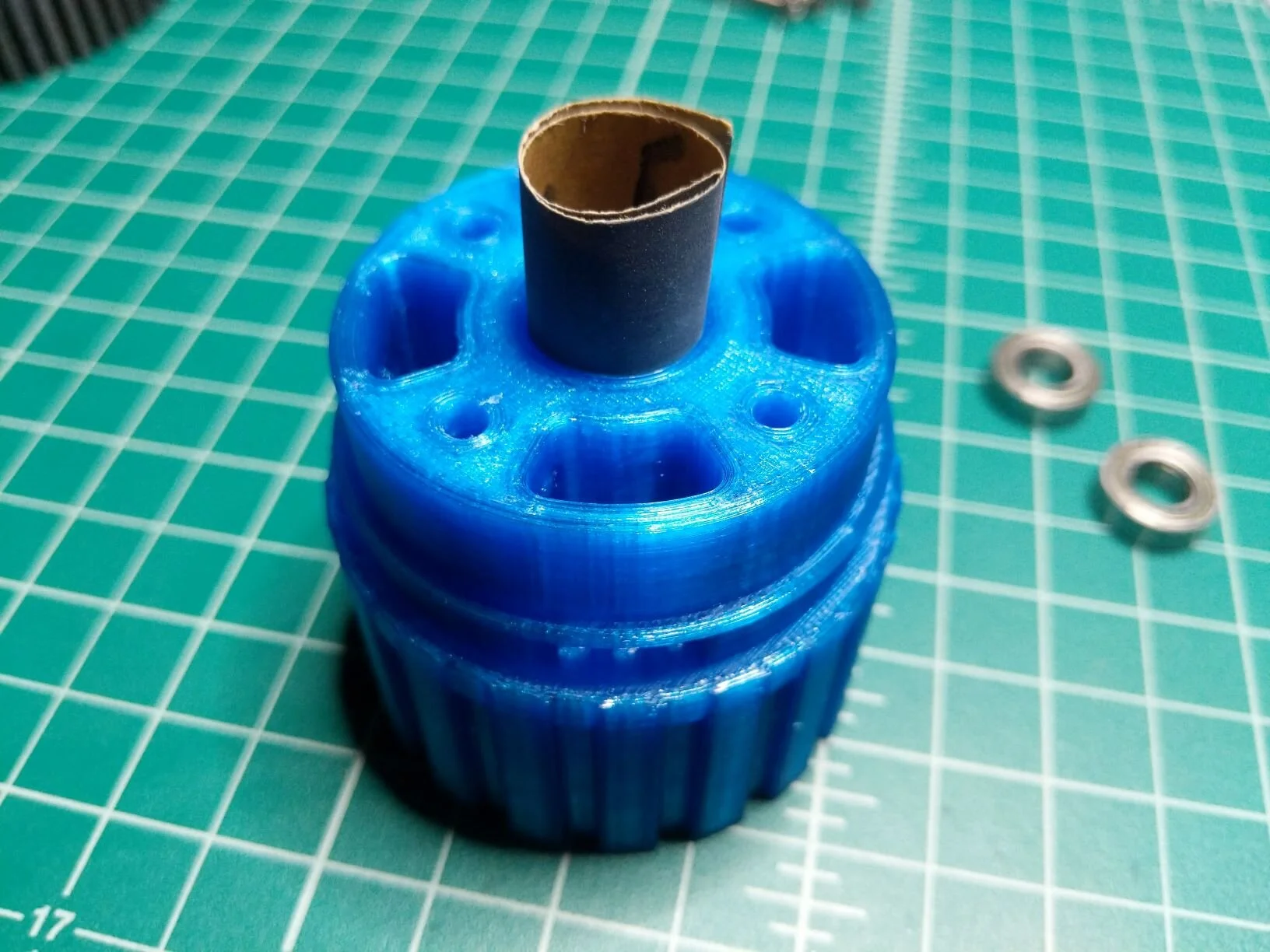
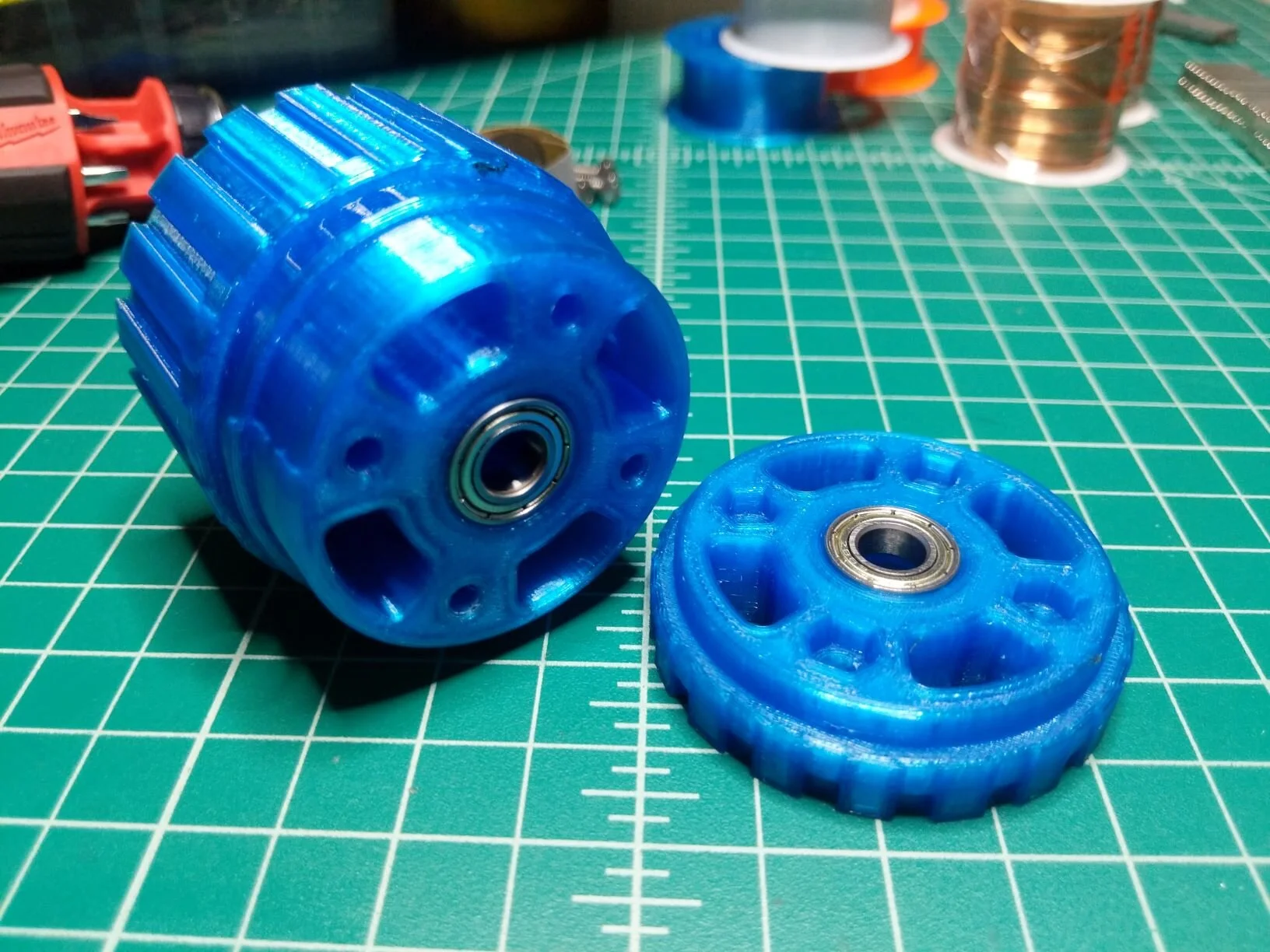
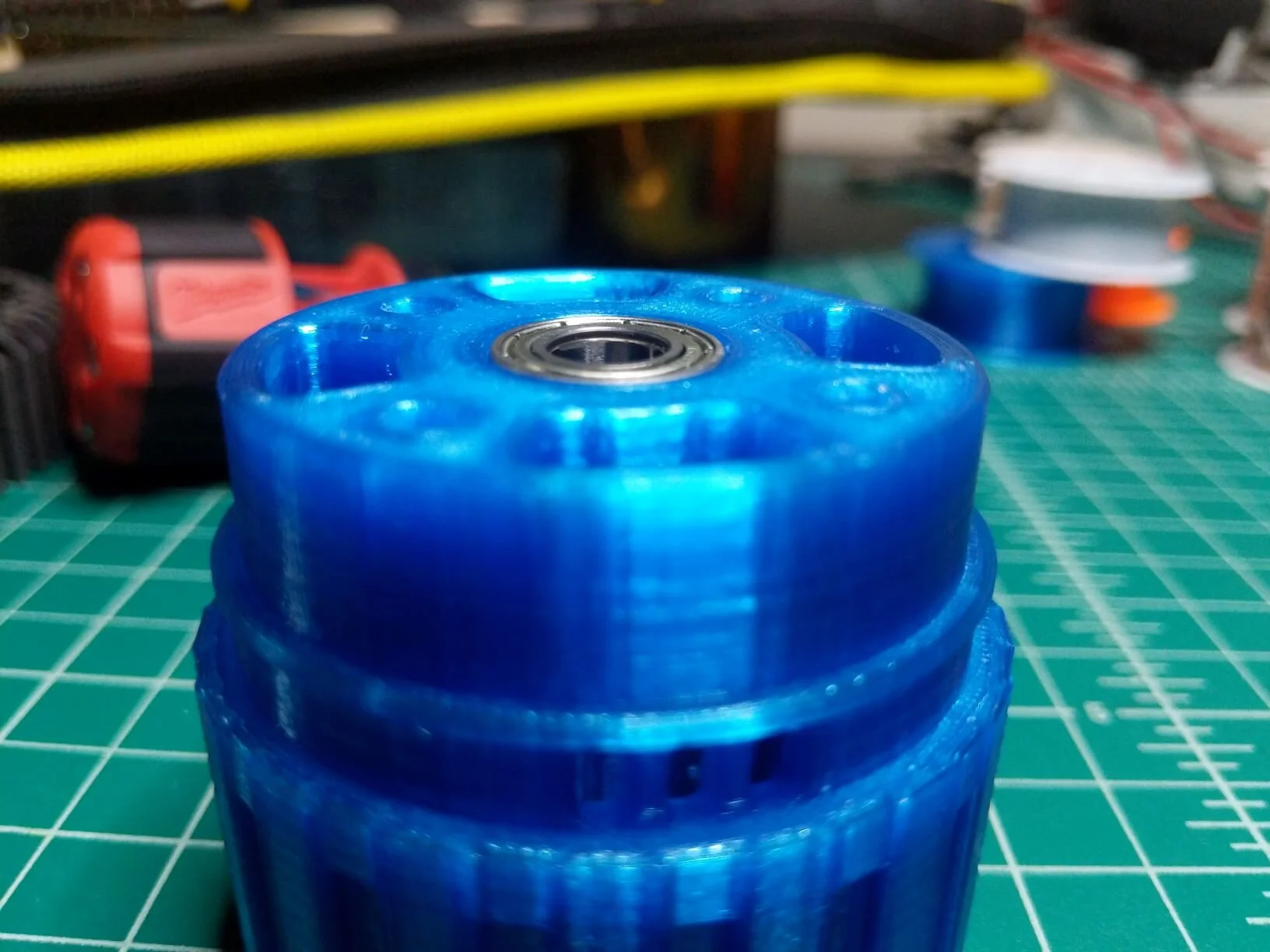
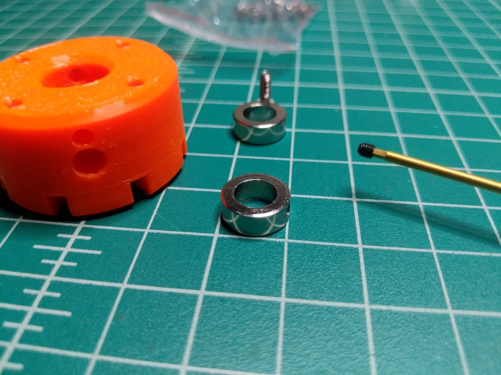
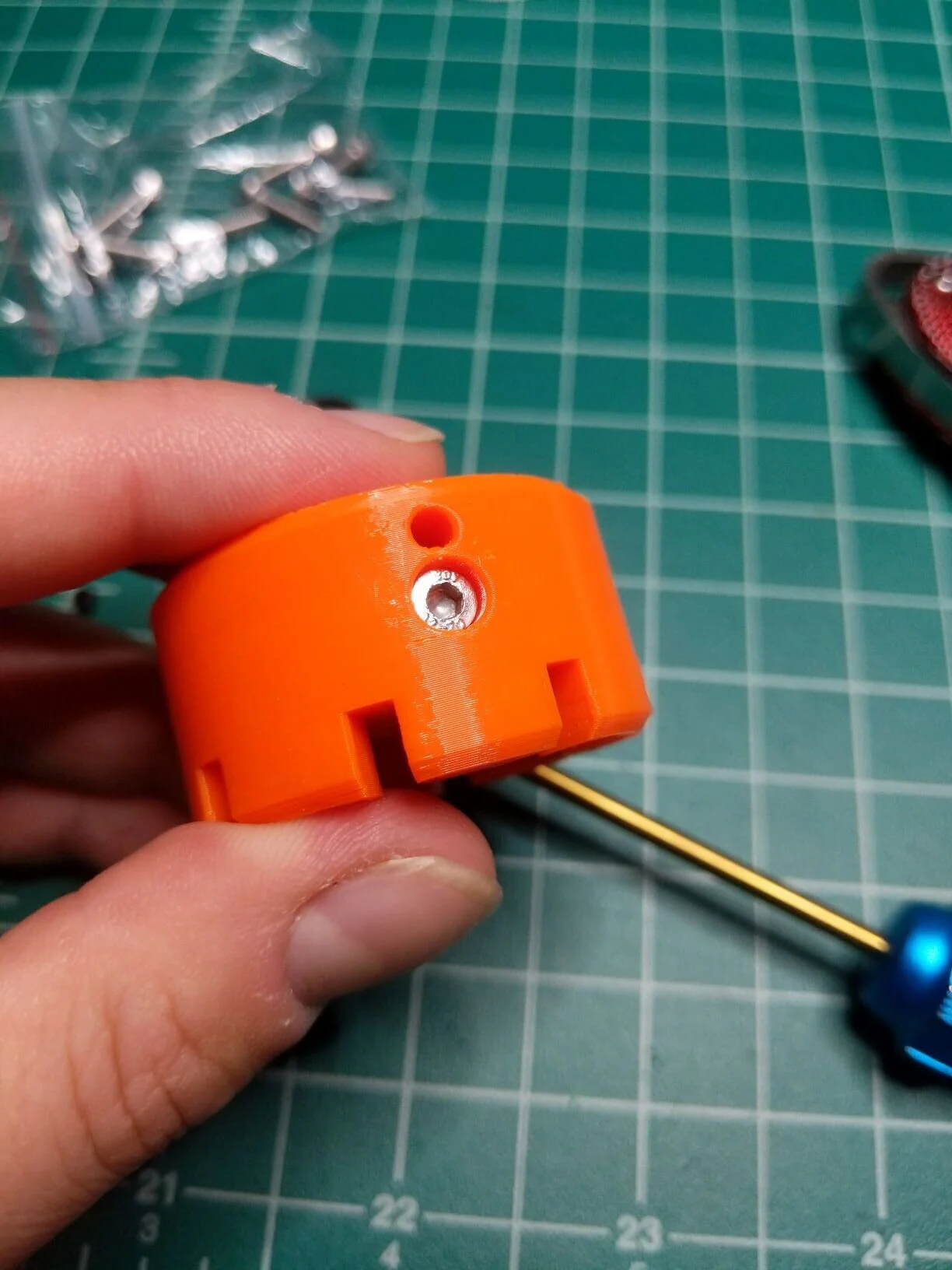
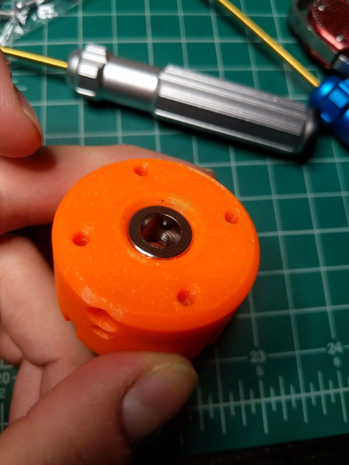
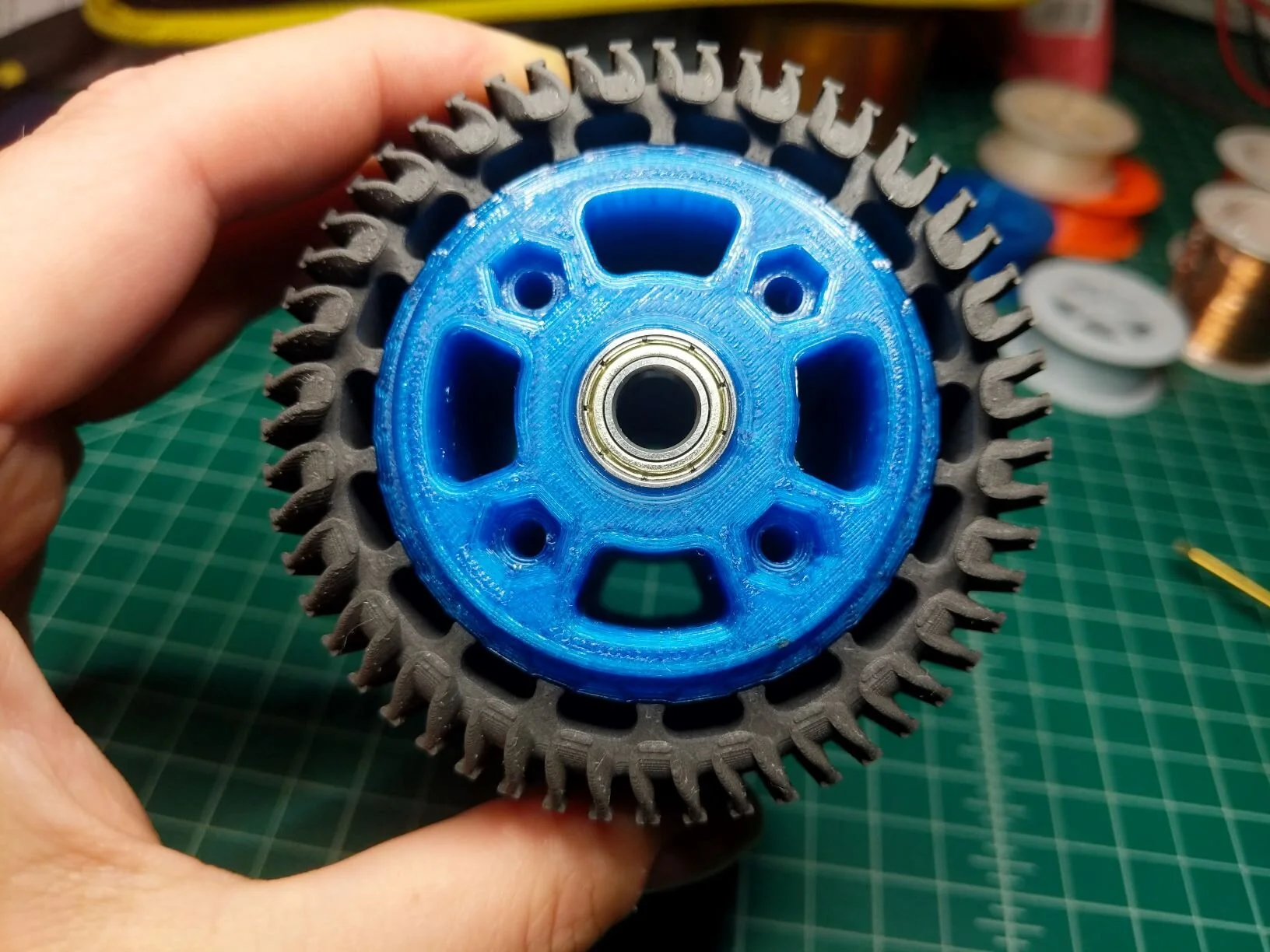
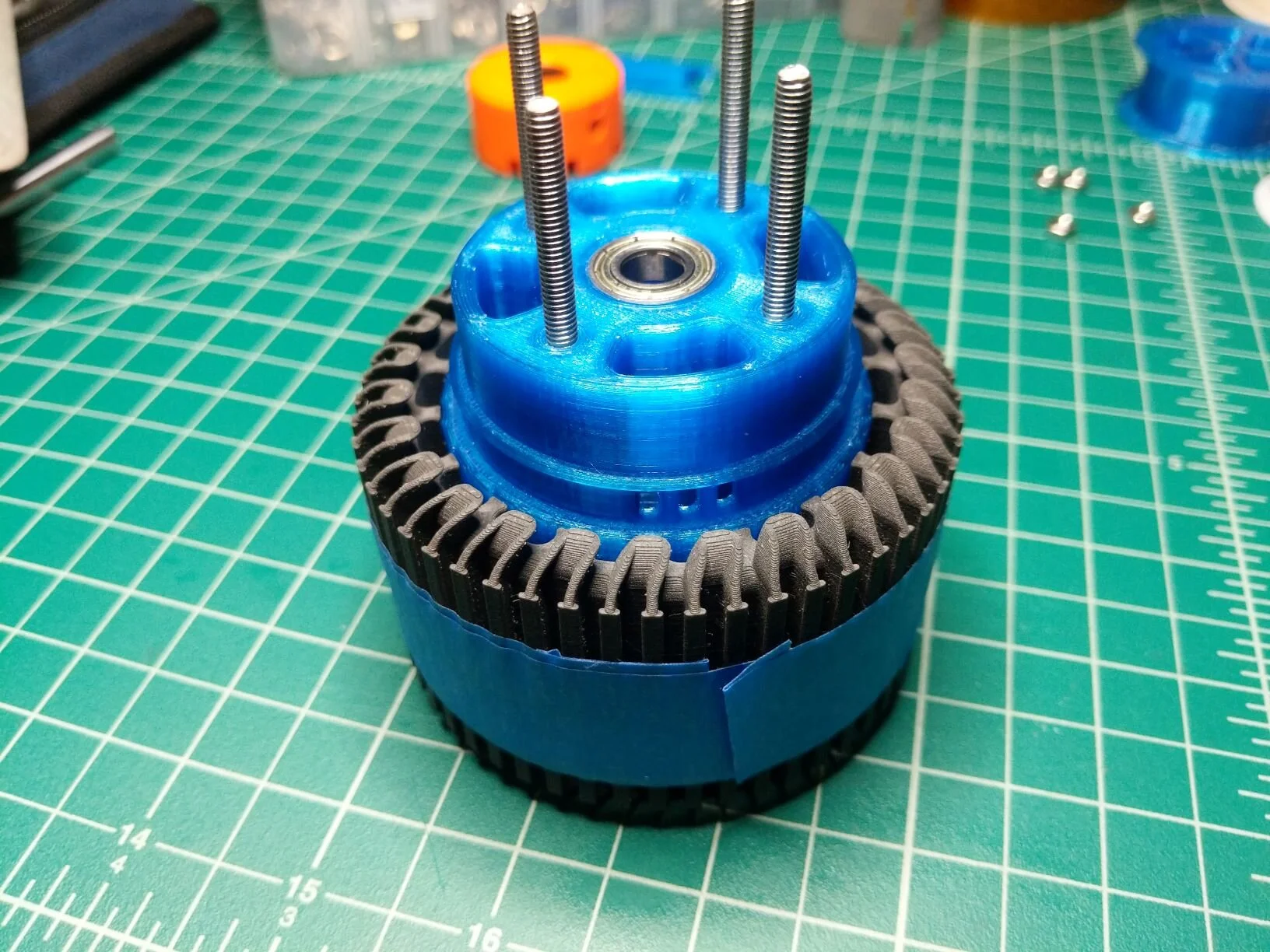
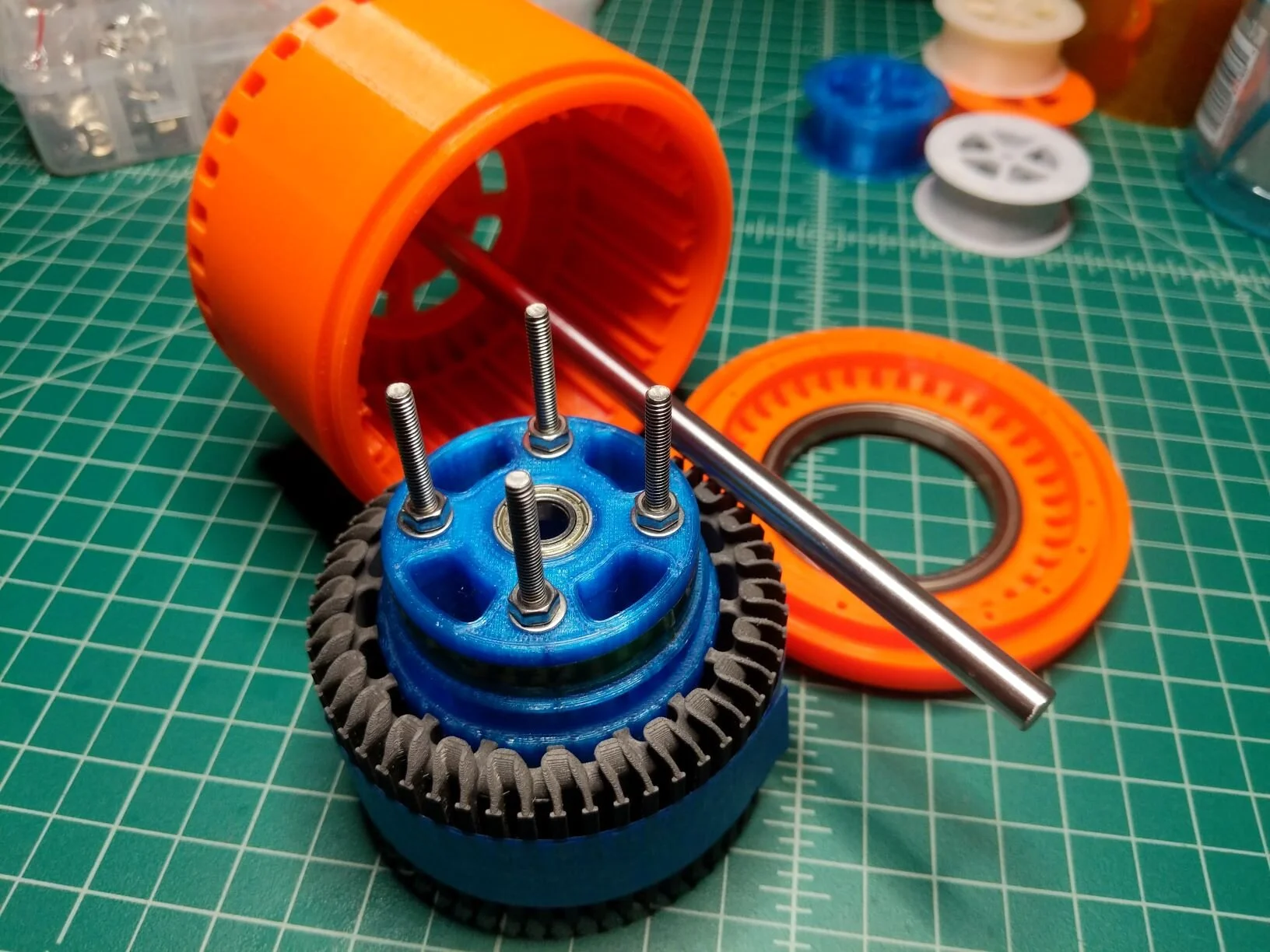
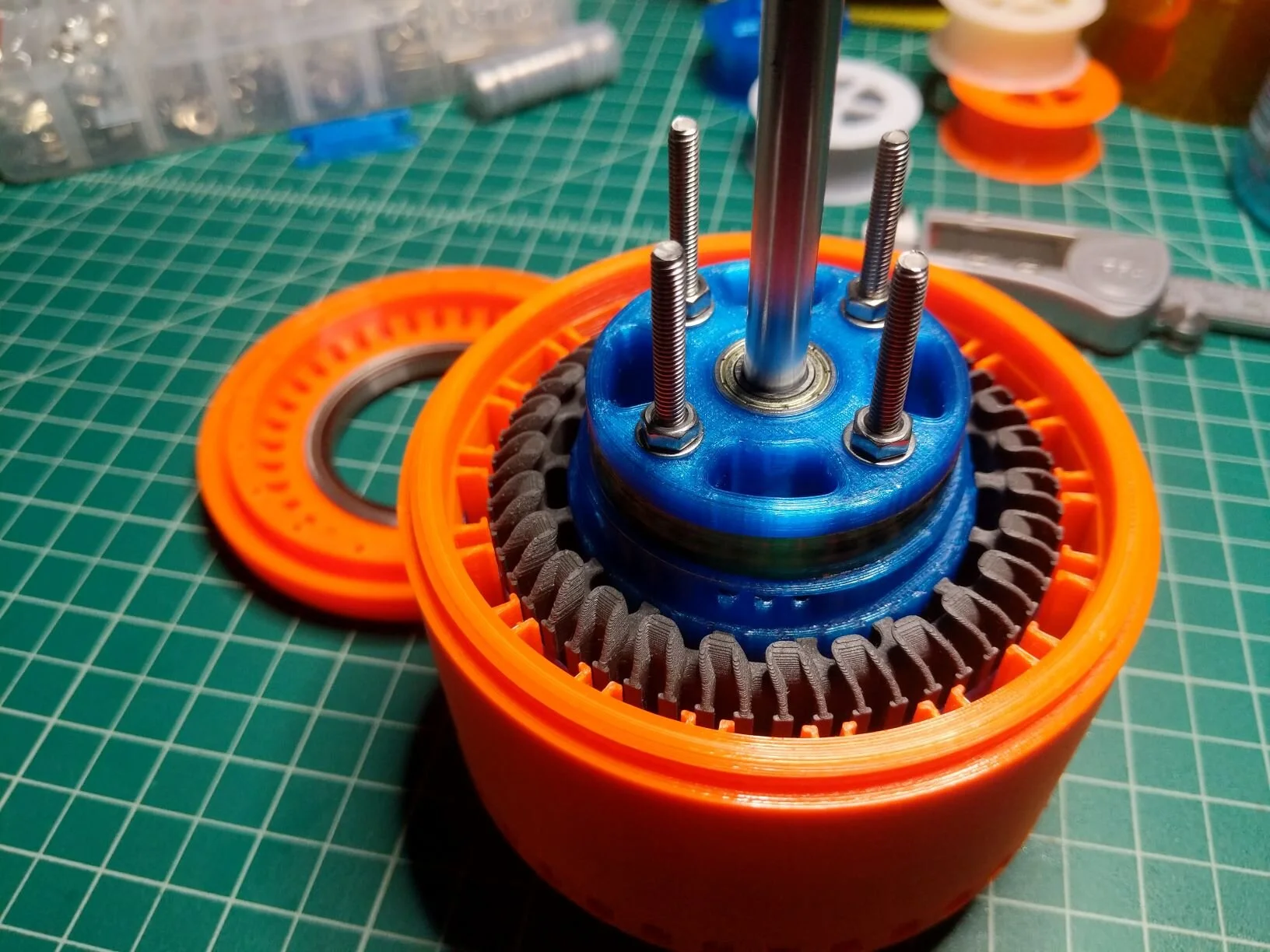
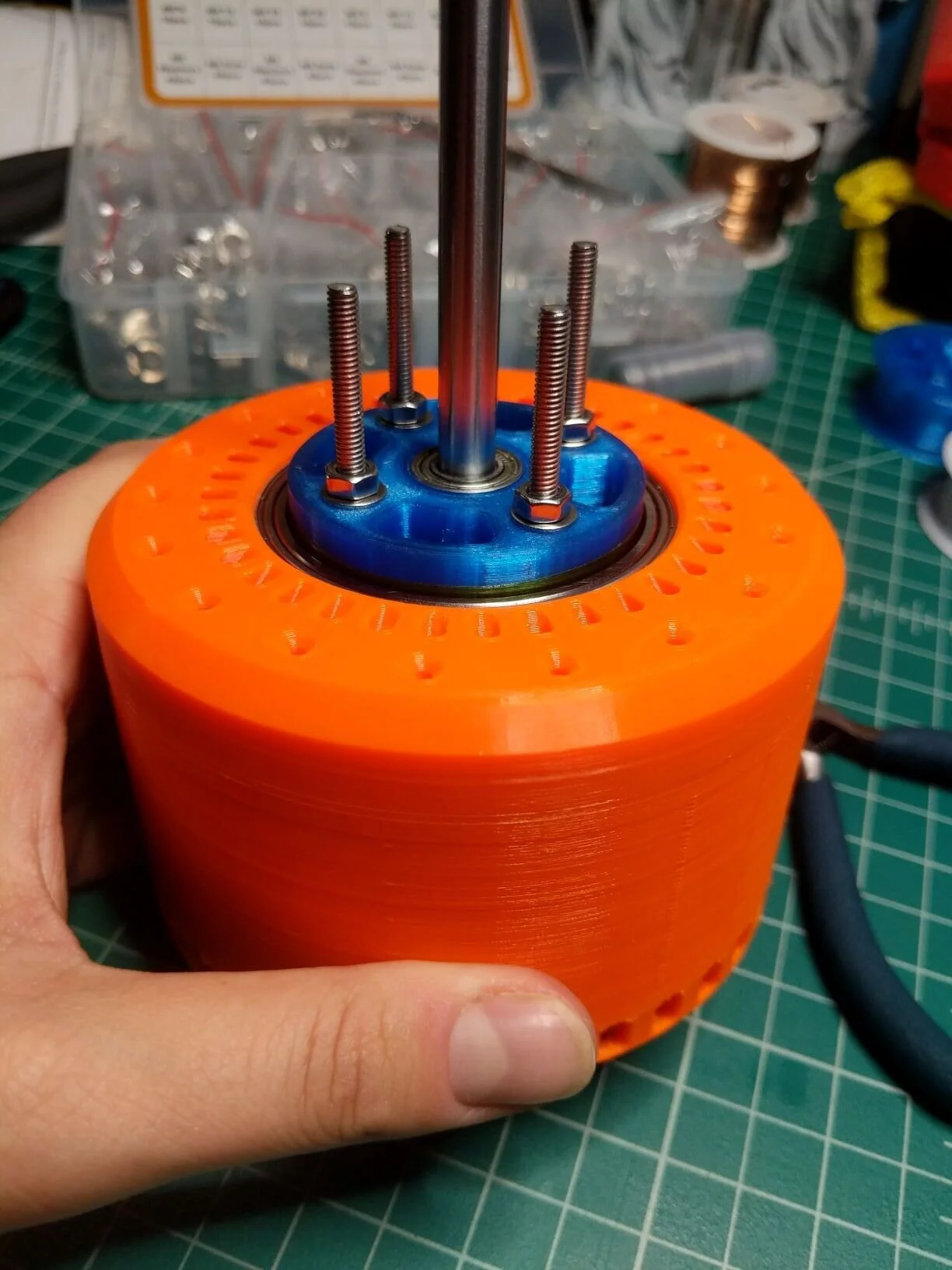
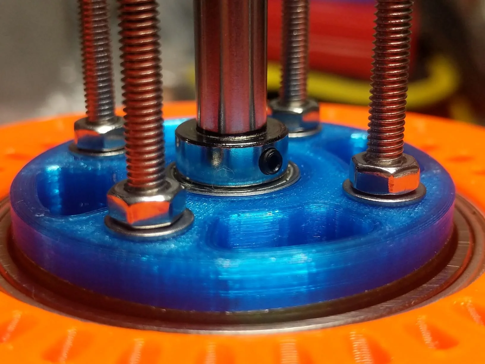
I’m not quite ready to run the copper wire through the core yet - still have some numbers to evaluate before i’m ready to commit. Until then, I did some basic fit checks with bearings, shaft rings, and core rotational clearance.









Next Up
I am holding off on running the copper through the core so I can focus on confirming the wire structure. When i’ve determine the proper length, and number of turns, for the wire, i’ll have a better idea of how difficult the winding will be. I figure i’ll practice using 3 separate strands of string, so i can practice the over-under pattern before I do the real thing.


